Rebuilding the TDR II after the mid-air crash
After overcoming my shock of the mid-air crash (explosion) and searching for how this all could happen. It was time to rebuild this great powerful machine. Luckily, at a first glance the crash was not as hard as I thought it would was. Some parts – which are usually known as unlucky parts that do not survive a crash – surprisingly survived, such as a main shaft, main spindle, Lipo tray and the main chassis. Of course it hurts to see your precious helicopter lying there in pieces. Nevertheless, I had to start rebuilding and making sure this will not happen again. I could not fix the canopy to support the SLS SPEED lipo’s, but I could adapt the Lipo’s and the battery tray in a proper way to cope with the canopy’s dimensions.
All necessary parts were ordered at Henseleit-helicopters, and new main blades at eRCmarket. The blades arrived in 2 working days whereas the German DHL took one entire week to arrive. However, the rebuilding could start.
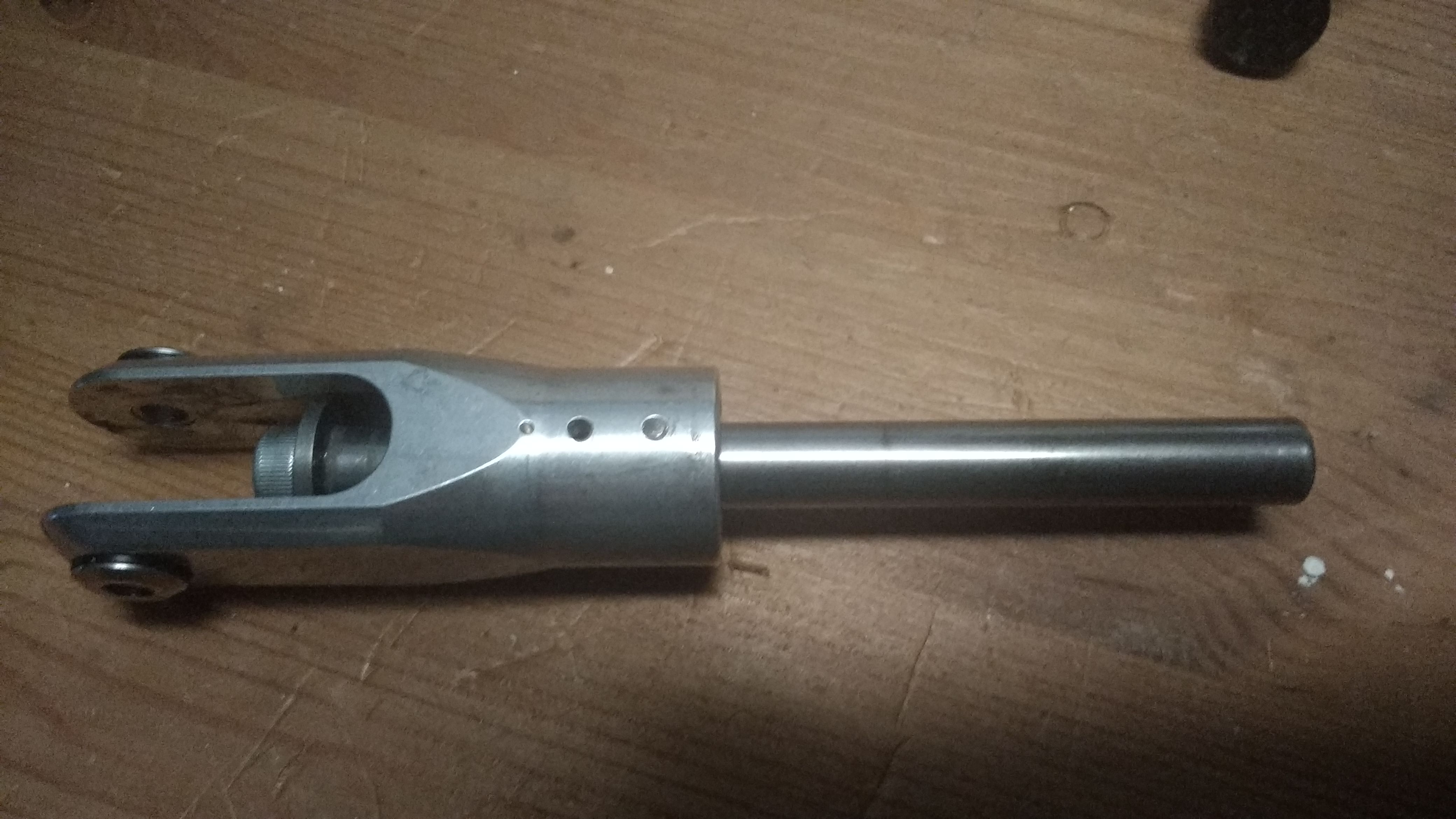
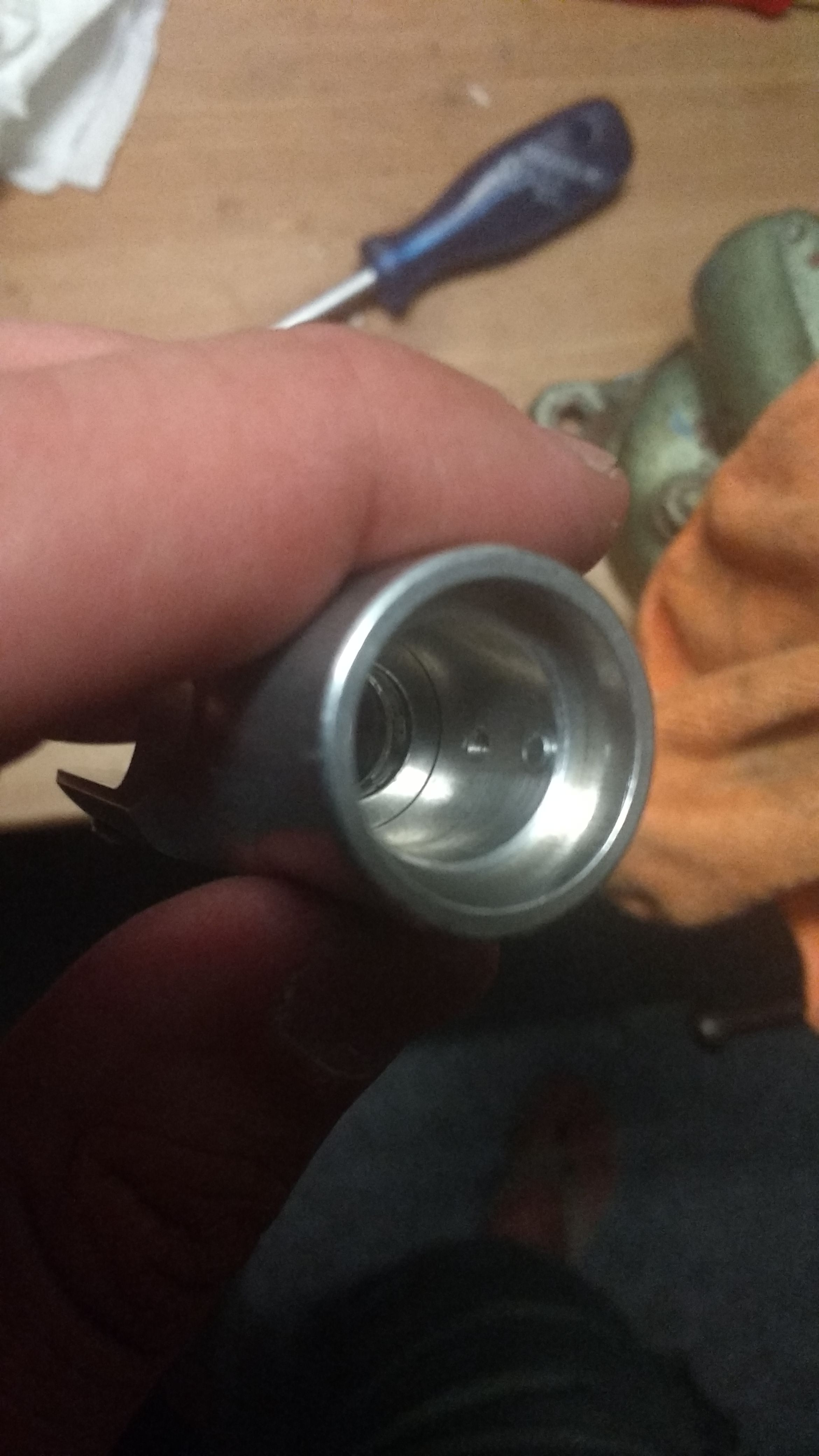
In the end it sounds more spectacular than it is. Everything went very smooth. Tail boom, and tail rotor replacement was an 1 hour job but the main rotor head had a small surprise for me. Something I did not notice before, is that the pitch arm had a broken screw and it was also lost. Although I did a proper inspection I never noticed it before. By unscrewing the pitch arm I noticed the screw broke at the most inconvenient spot. The spot where it was impossible for me to get any grip on it for extracting the screw.
I tried a couple of things:
- Heat it up with a propane gas burner
- Try to get a grip from the inside
- Drill the screw out with all kinds of tools
In the end nothing worked so I took it to work where some mechanical geniuses always have a solution, some extra ideas and tools. They got it out, but with some extra modifications, making the hole taped to a 3,5mm. However, this was solved again with the insertion of adapter winding to make it 3mm again.
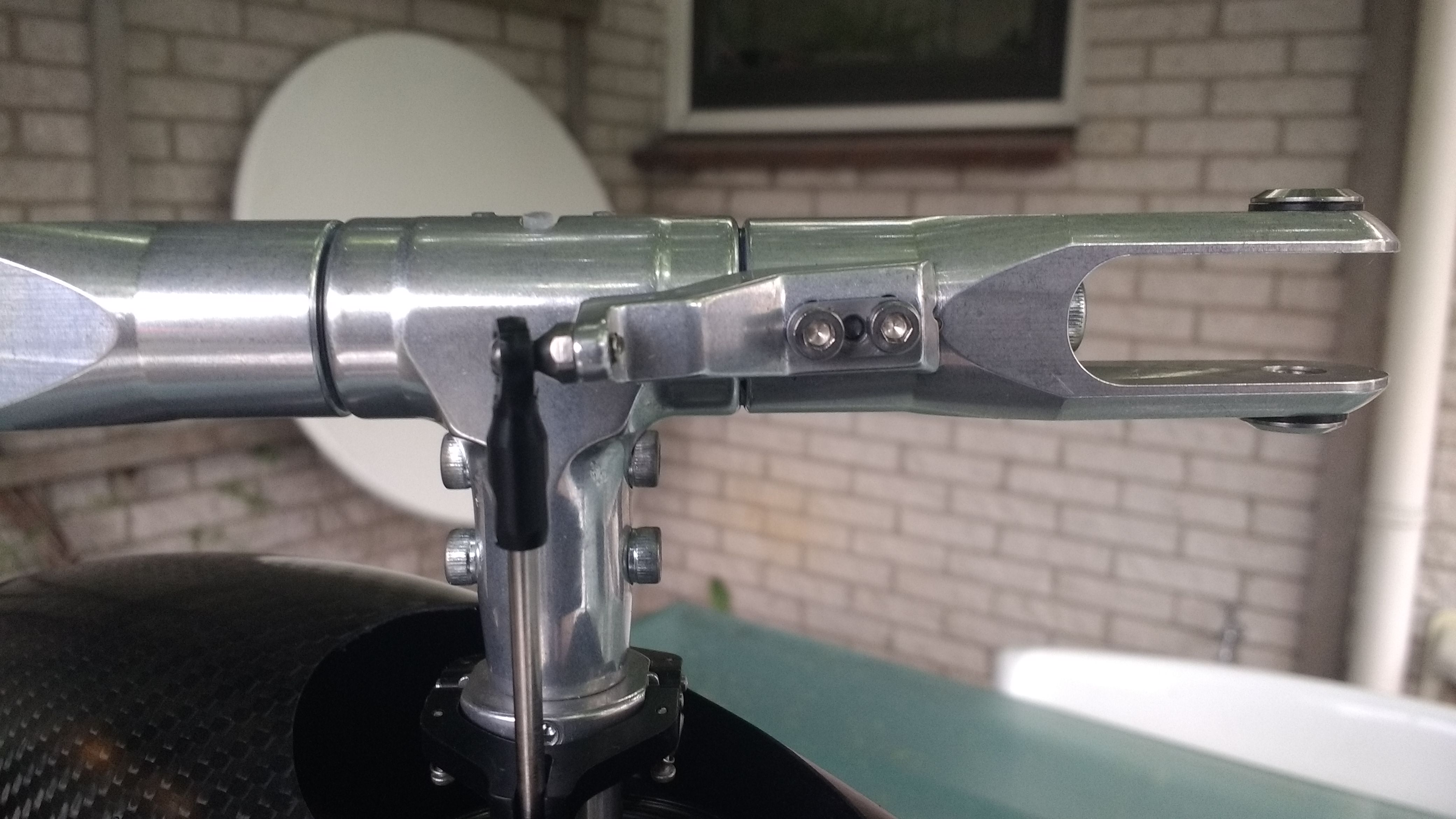
This resulted in a small offsite of the pitch arm. I decided to accept it and take another look in the setup phase if this small offset influenced the calibration.
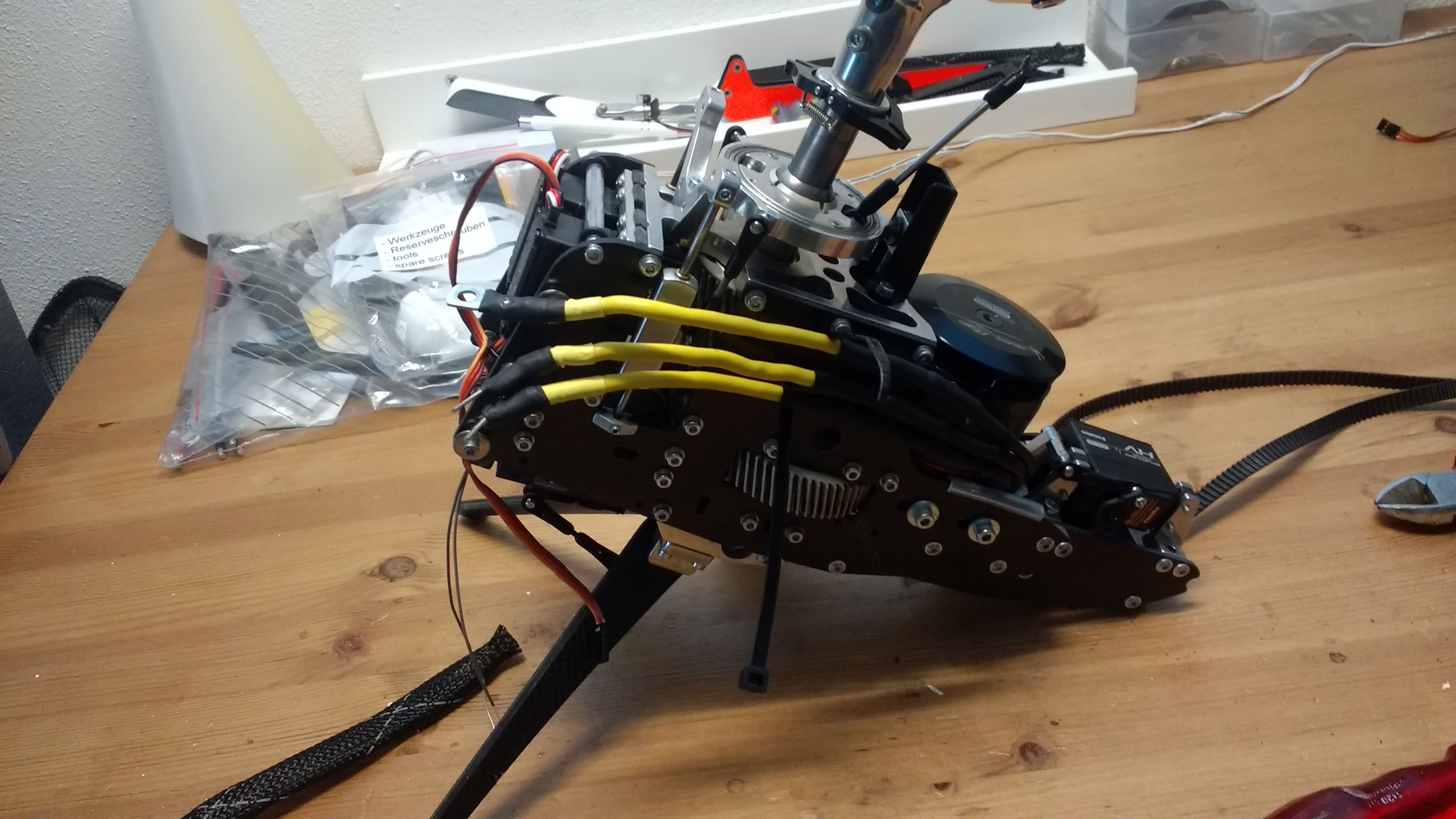
One other important part which I had to pay some attention to was that the new (Carbon) canopy will not be adapted with some extra holes to fixate the canopy around the other mechanical parts, so I adapted the mechanical parts to fit the canopy. I did this by taking out the stiffening frame 0260.
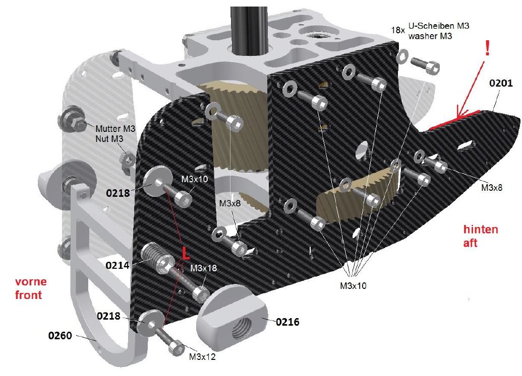
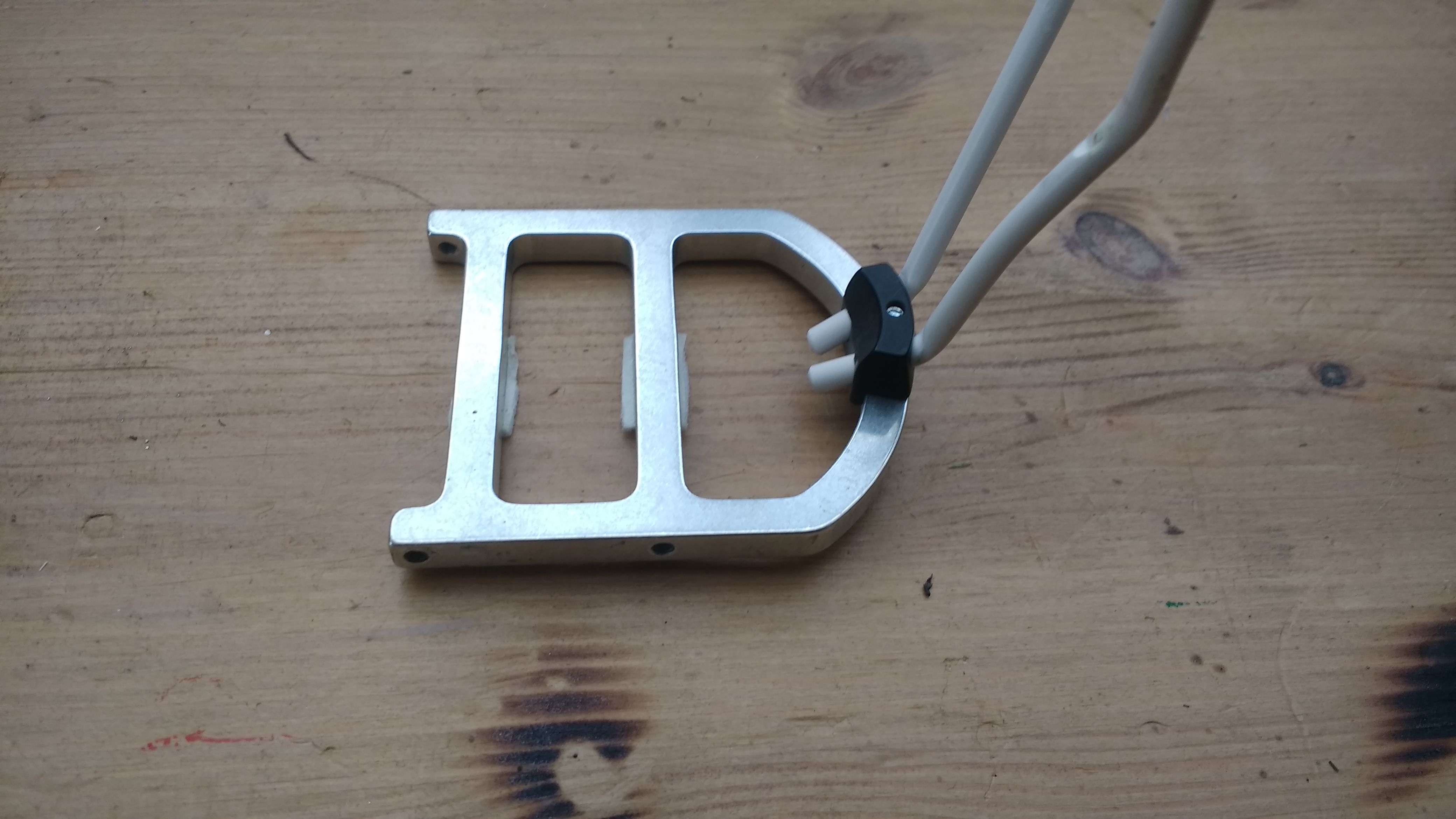
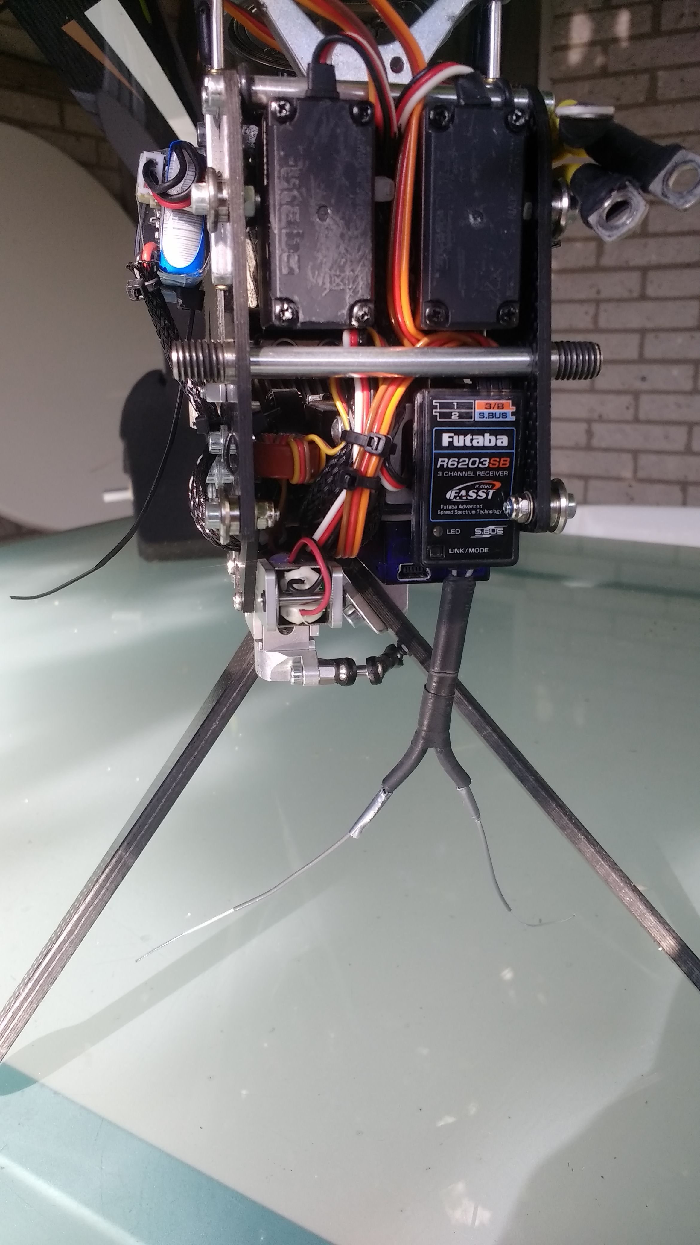
By leaving the stiffening frame out, the batteries could can be placed around 1cm more backwards in the tray so that the canopy fits very tightly!
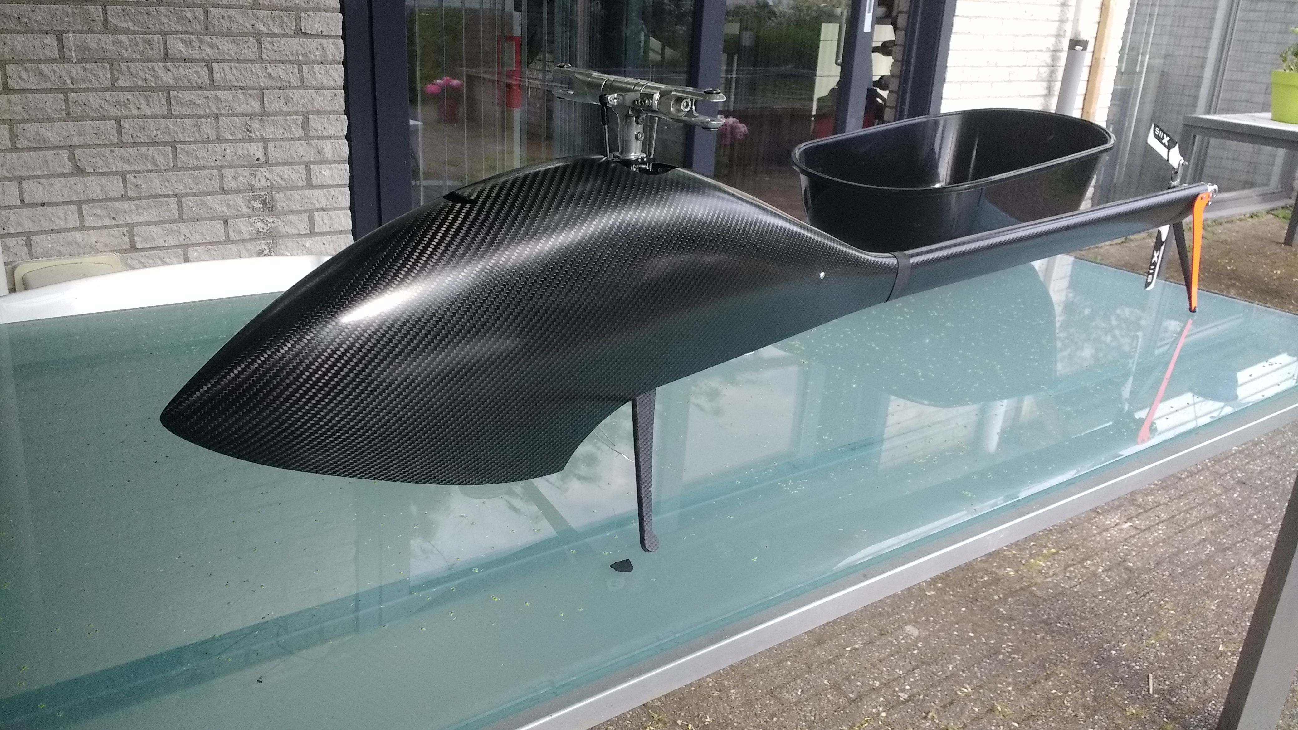
The canopy fits, check! Now I could make an appointment with the airbrush guy (Airbrush Flevoland) to have it painted nicely and I could continue with the setup. These results will be shown later.
Plan for the setup:
- Low RPM 3D => 12 degrees pitch
- mid RPM 3D => 13,5 degrees pitch
- SPEED RPM => 16 degrees pitch 😉
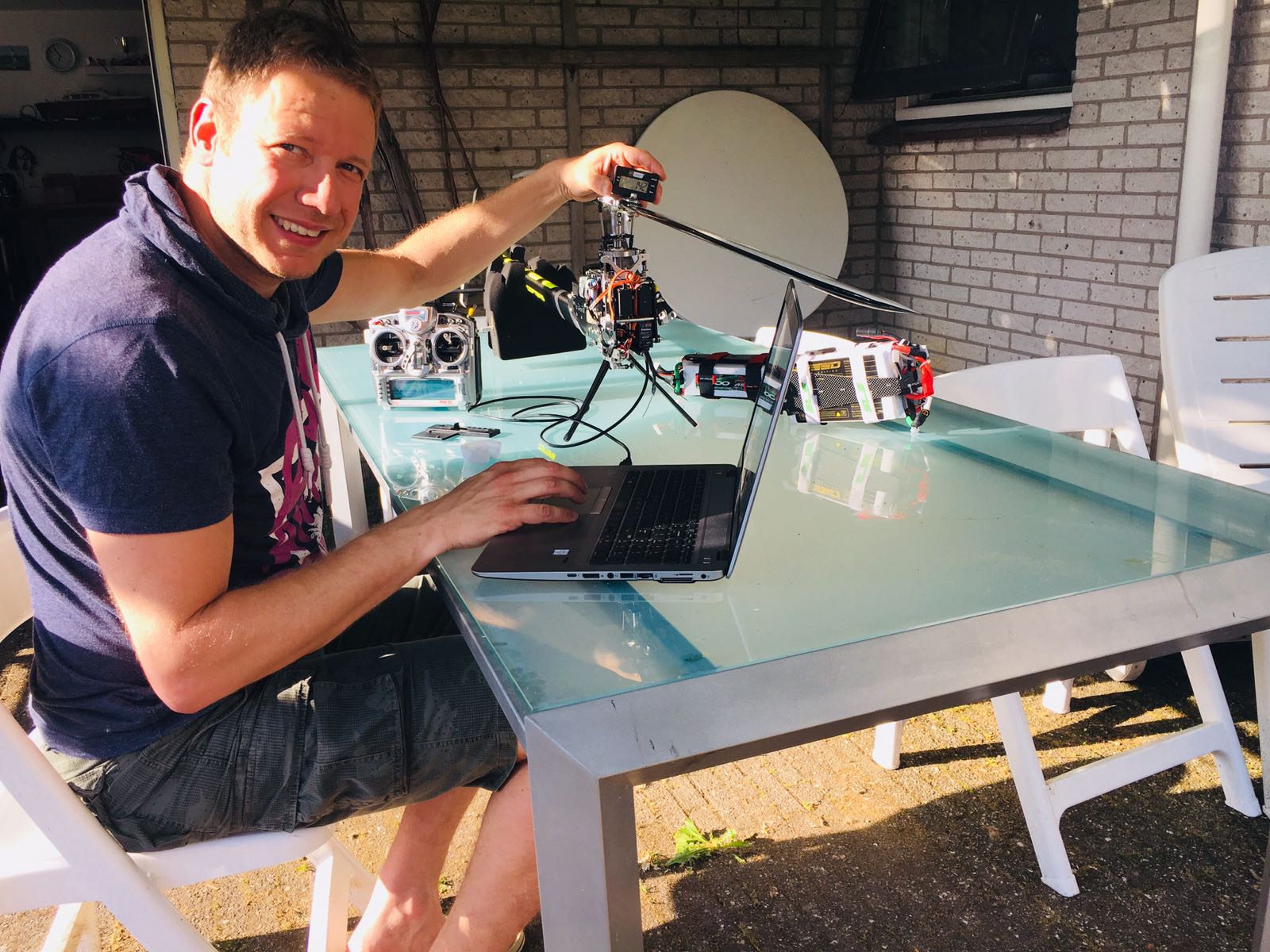
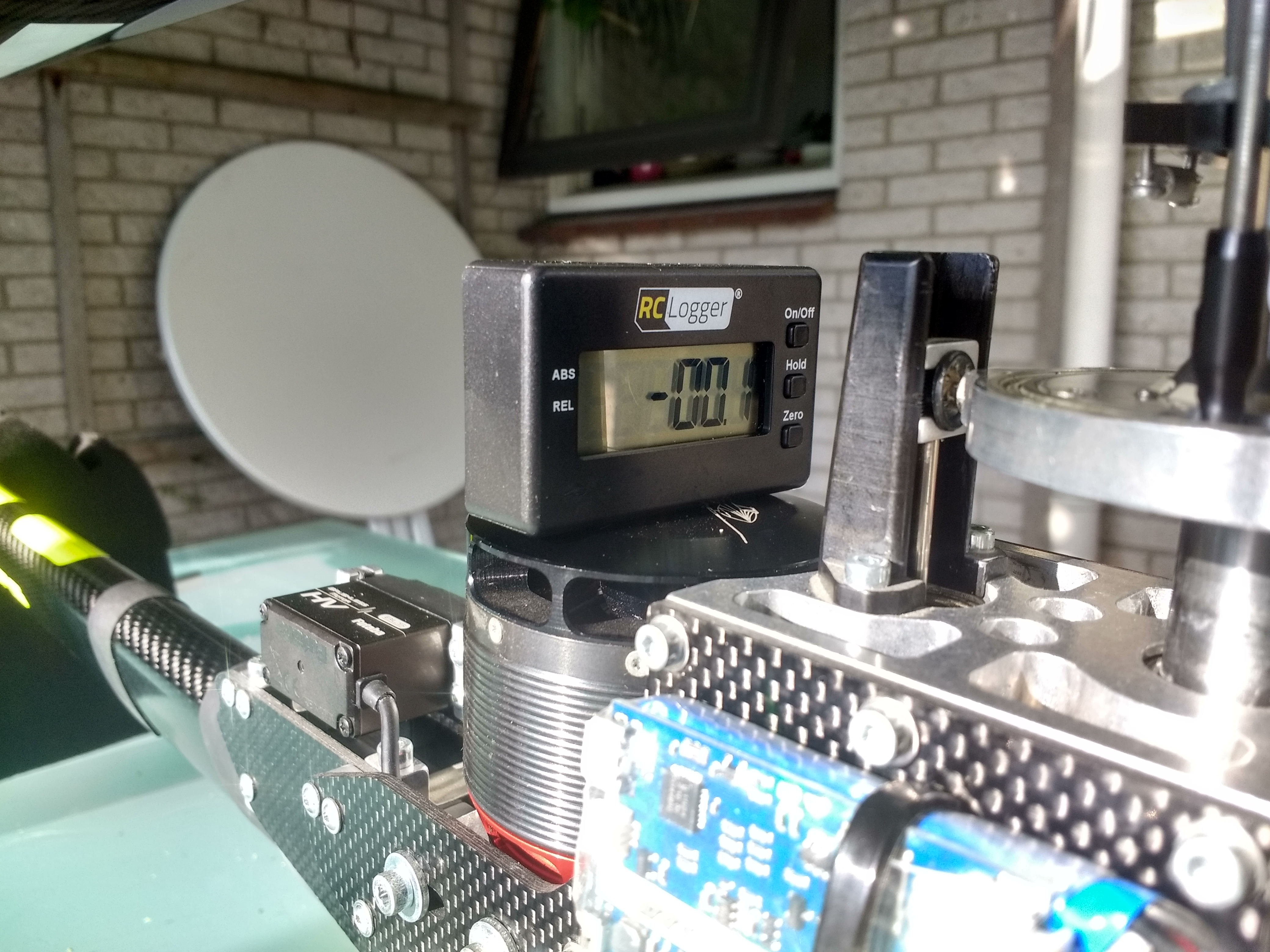
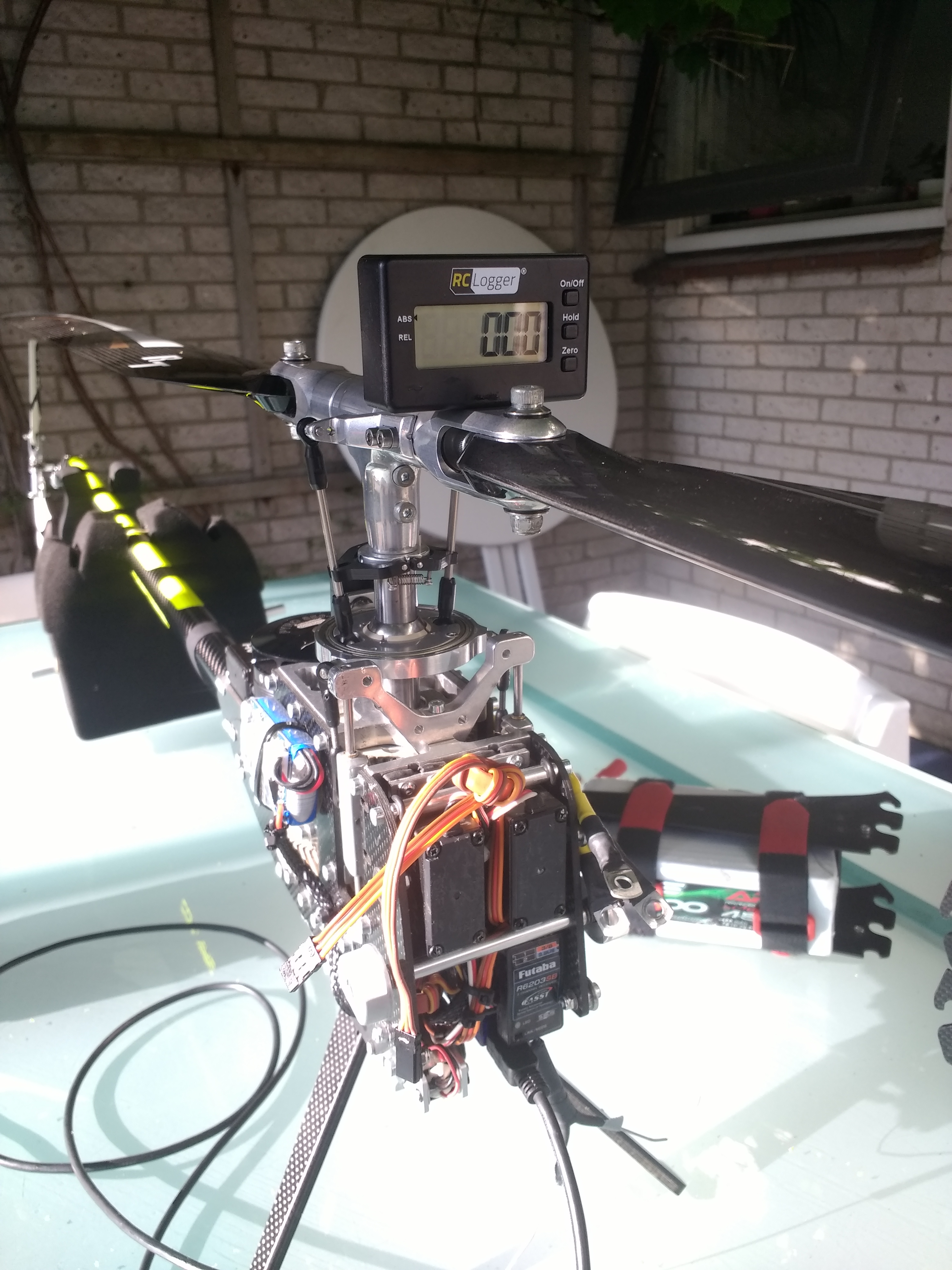
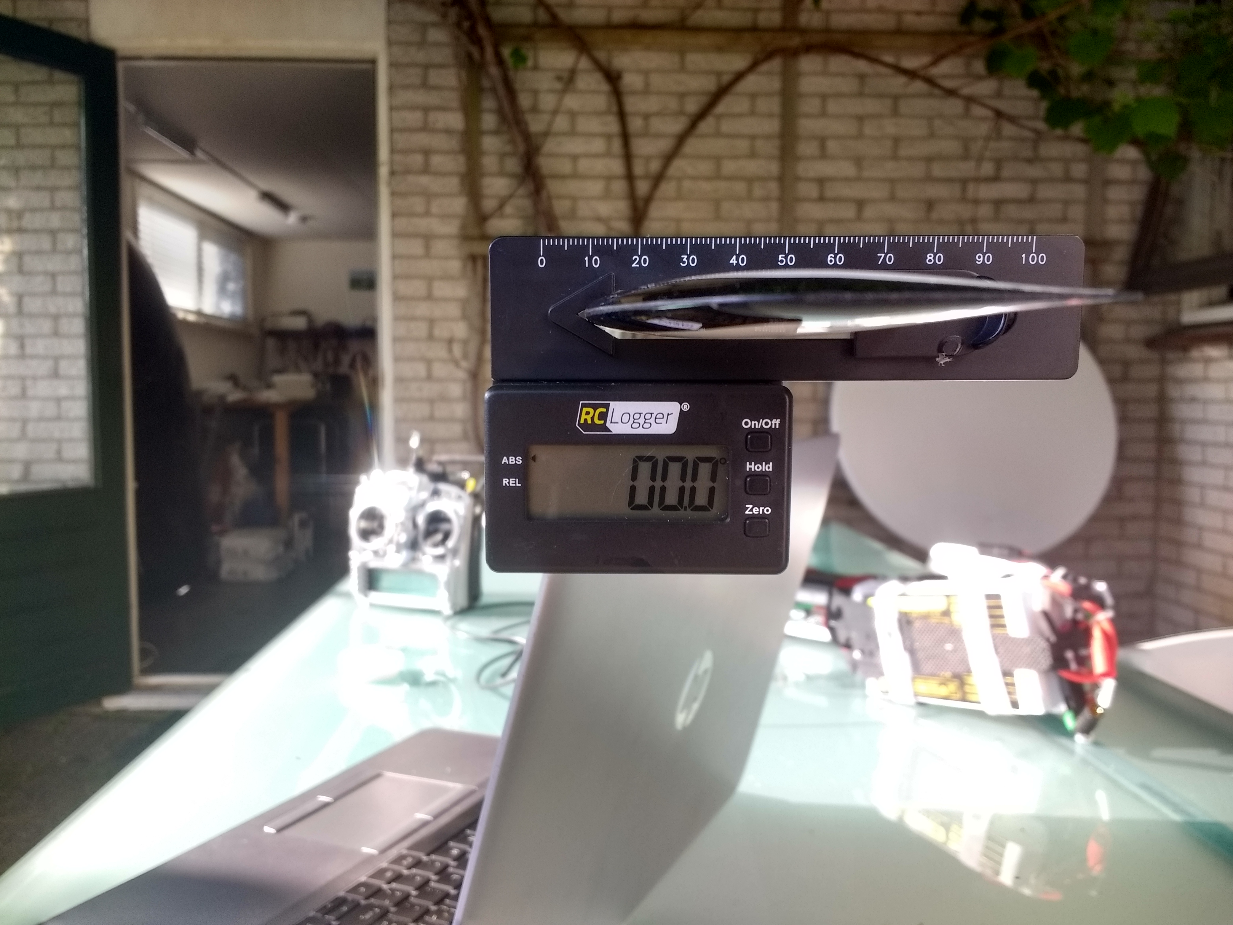
My fear was that the offset of the pitch arm would influence the calibration setup in a negative way. I thought it would not be possible to make positive and negative pitch angle be linear and identical to the other pitch arm. By first leveling the swash-plate horizontally and making sure that the blade grips were at 0 degrees…
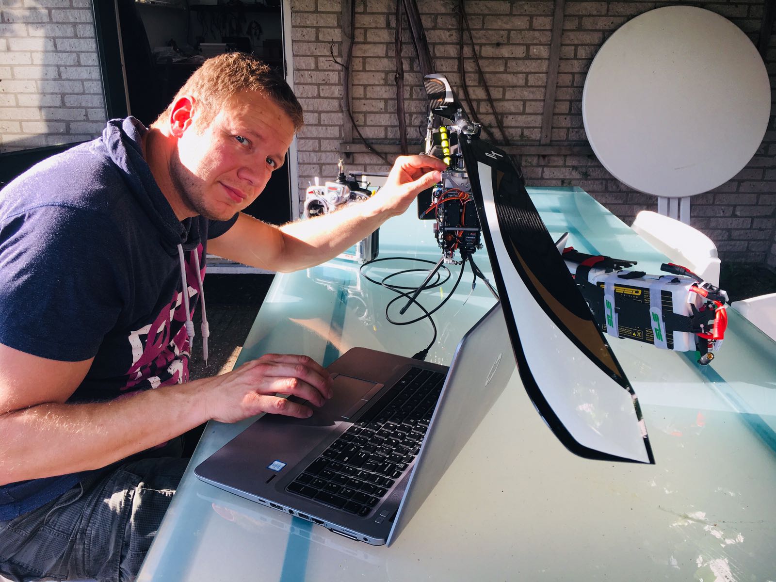
I was positively surprised that the positive and negative pitch angle where completely linear. The setup has never (also on other helicopters) been that good. All angles (negative and positive) for both blades turned out to be within 0.1 degrees tolerance. WoW.
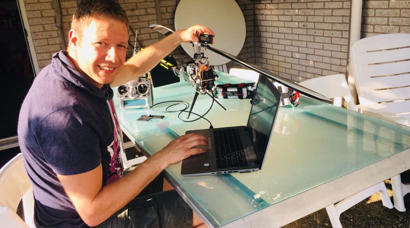
Way of working:

Now it’s time to place the refurbished Kontronik kosmik speed controller back in to place. This is the last part of the rebuilding part before testing. With the speed controller in place I can test if the helicopter runs smoothly and without vibrations. This is always the biggest guess afterwards.